1. TMC 2009 should solder PDN to utilize UART mode, but there are two soldering ways in the manual, which one should I choose?
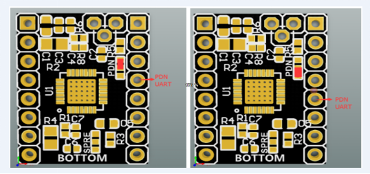
Because the default PDN of our company's motherboard driver port is the fourth pin, the upper part is welded. The PDN of other brands’ mainboard is the fifth pin. So we put two pictures to distinguish them. And the UART model TMC 2209 we sell is the upper part of the welding. If you don’t use our mainboard, you had better purchase the regular mode TMC 2209. The regular model can also use UART mode through soldering PDN.

2. How does TMC 2209 use Silent Mode and High Speed and Anti-Shake Mode?
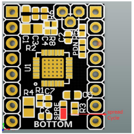
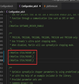
The factory default uses silent mode, as shown on the left side of the figure below, and needs to enable the command line of silent mode in the firmware.
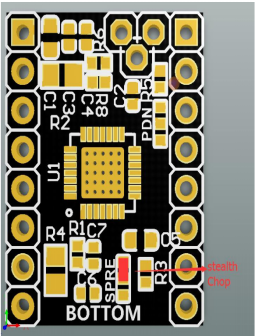
If you want to use the High Speed and Anti-Shake Mode, you should remove the resistor and solder it to two bonding pads, and shield the command line of the silent mode in the firmware.
3. How does TMC 2209 normally utilize a limit switch?
When using the limit switch function, you need to cut down the blocking rotor detection pin, so that the mechanical switch can work normally. The operation method is shown in the below picture.
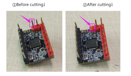
However, when the mainboard has a DIAG pin, you don’t need to cut this pin, for example, in the Octopus series, if you insert the DIAG jumper cap, you could normally use the blocking rotor detection pin function.
4. TMC 2209 driver reports an error, showing a TMC connection error.
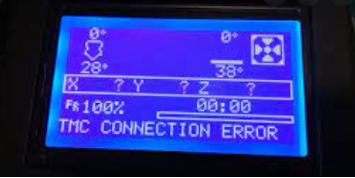
The reasons causing this problem.
1) When you supply power to the circuit board with USB, which will show this reporting error. Because the driver only works under the supply of mainboard12V or 24V power.
2) If there is a problem with a particular axis, you could send the M122 command in the terminal to check the driving status or move each axis with the controller to see which axis appears abnormal.
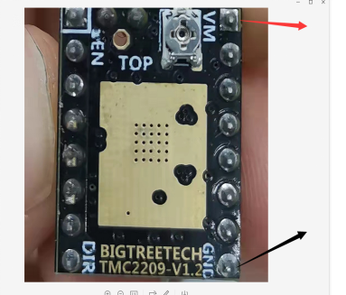
5. How to judge the quality of TMC drivers? How do measure the voltage or current of the driver? The quality of the driver could be tested by a multimeter. Use the buzzer file to test the continuity of VM and GND. The driver voltage is also measured on these two pins. The driving current can’t be tested, but it can be checked in the firmware. If you use our TFT screen, you could check the driver’s current, either.
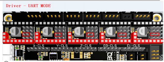
6. How to insert jumper caps when TMC 2209 used Uart mode?
Take the SKR 2 mainboard as an example, insert the jumper cap inside the red box, as the picture shows.
Purchase Link:
Navigation:
- BIQU Official Website http://biqu3d.com
- BIGTREETECH Official Website http://bigtree-tech.com
- Online Store https://biqu.equipment
- Community https://community.biqu3d.com

Comments
0 comments
Please sign in to leave a comment.